Arduino Project 1: Heat Seeking Robot (Part 1)
Be advised This post is quite old (21 Jul 2012) and any code may be out of date. Proceed with caution.
After finishing a cheerlights project for the GE Healthcare Tech Conference back in April, I had a pretty strong interest in doing more with Arduino boards. I visited many sites and read several blogs looking for inspiration for a project - I wanted to do something new, without going too crazy (this is my first stab at robotics).
Then I stumbled on an article about an IR thermometer being used with Arduino. I quickly decided I was going to do something with an IR thermometer... a heat seeking missile! Oh wait. Too dangerous.
I settled on a heat seeking vehicle. Simply put, a wheeled or tracked vehicle that would scan an area, look for areas above a certain temperature (to identify human bodies), and then drive towards that point (person).
Here are the supplies I bought in preparation:
- Hitec 31055S HS-55 Economy Sub Micro Universal Servo - $11
- Arduino Uno R3 - $21
- 2 Male DC Plug to 9v Battery Clip - $5
- 400 point bread board and jumper wires - $9
- Double gearbox with 2 DC motors - $9
- Tamiya tracked vehicle kit - $20
- Motor shield for Arduino, by DF Robot - $17
- MLX90614 IR Thermometer - $20
For a rough total of $112. You'll also need about $2 worth of resistors, which we'll get to shortly.
First Things First
You have to crawl before you can walk. To get started, I simply wanted to wire up the IR thermometer and do some testing. Full disclosure - I stood on the shoulders of giants throughout this project.
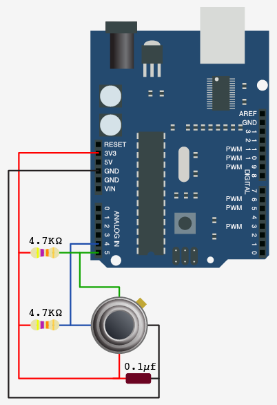
I followed a tutorial I found on bildr to get the basic IR thermometer wiring (PS, bildr.org is awesome, and they do a great service to the world). From a hardware pespective, the IR thermometer has 4 pins: a ground, voltage in (V-in), a "data" pin, and a "clock" pin. See the diagram below from bildr:
- the V-in is the red wire, plugged into the 3.3V power supply on the Arduino.
- the ground is the black wire, plugged into any of the "GND" connections on the Arduino
- the blue line represents the "data" connection and should be connected to pin 4 on the Arduino
- the green line represents the "clock" connection and should be connected to pin 5 on the Arduino
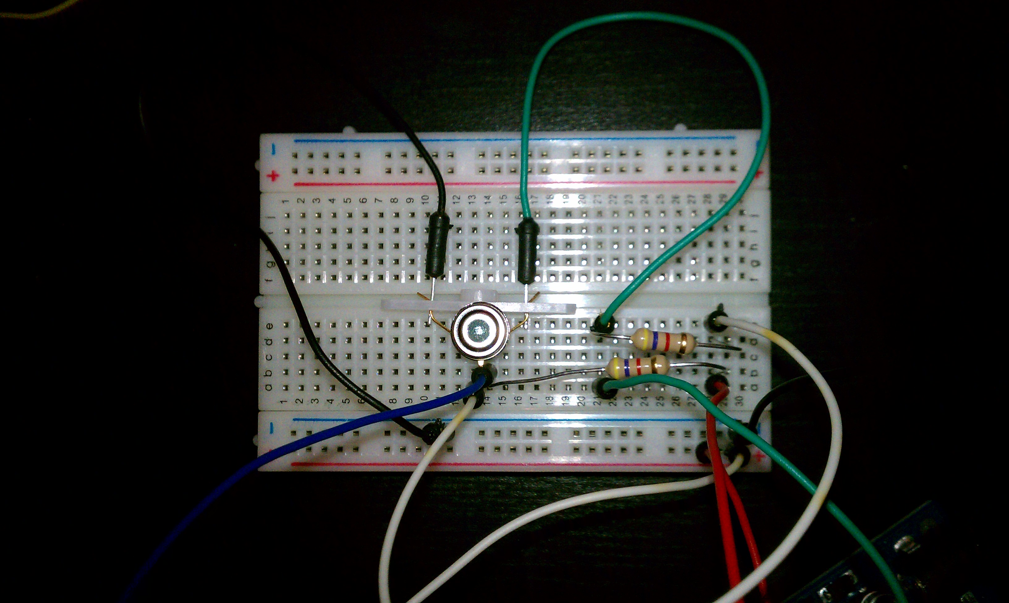
You'll also notice that the data and clock connections are connected to the V-in wire via 4.7 K Ohm resistors; these are called "pull up resistors". Last, the good folks at bildr included a small capacitor between the V-in and ground, but the thermometer should work without it. You'll probably want to do all of these connections on your bread board, since we're prototyping and don't want to do any soldering yet. Check out my build here:

Notice the bands on the resistor - yellow, purple, red, gold. This is resistor shorthand. Yellow represents 40, purple/violet is 7, red is a multiplier of 100, and gold indicates the tolerance. So these resistors are (40+7)*100 Ohms, or 4700 Ohms, or 4.7K Ohms, with a +/- 5% tolerance. I tried to replicate the colors used in the bildr example for clarity.
Alright, the IR thermometer is all wired up and connected to Arduino, the hardware portion is complete. Download all the files, including the sketch and the I2C master library from the bildr post. Don't forget to place the I2C master files in your Arduino libraries directory and restart your Arduino IDE. Now for a quick test:
Awesome! Basic temperature reading functionality established!
In Part 2, we'll incorporate the motor shield, the servo, and the chassis kit to finish the heat seeking vehicle.


Leave a Comment