
Arduino Project 3: Accelerometer Primer
This project is more of a warm-up than a full-blown project. I wanted to get a feel for the basic workings of an accelerometer in preparation for a larger undertaking (no spoilers!). I borrowed this project idea from a forum about Arduino and accelerometers but can't remember which forum, so I can't credit back to the original poster - sorry about that.
Before we get to the how, let's take a look at the what. Basically we have an accelerometer and 5 LEDs mounted on a breadboard. Four of the LEDs are mounted to correspond with the X and Y accelerometer axes and one LED is in the middle. When the accelerometer is level, only the middle LED is illuminated. If you tilt the accelerometer to the side, the LED on that side is illuminated.
Remember the accelerometer measures force, not tilt - we can demonstrate this by quickly moving the accelerometer to one side, creating lateral force. The LED on the opposite side relative to the direction we move the board will illuminate - that is, if we move the board to the left, the LED on the right will illuminate.
Let's move on to the how. Here are the parts I used:
- Virtuabotix MMA7361 Three Axis Accelerometer Module - $10
- Arduino Uno R3 - $26
- 400-point Breadboard with Jumper Wires - $9
- 5mm LEDs with Resistors (5 Colors, Pack of 25) - $7
Total project cost of $52, plus you'll have some leftover jumper wires and LEDs.
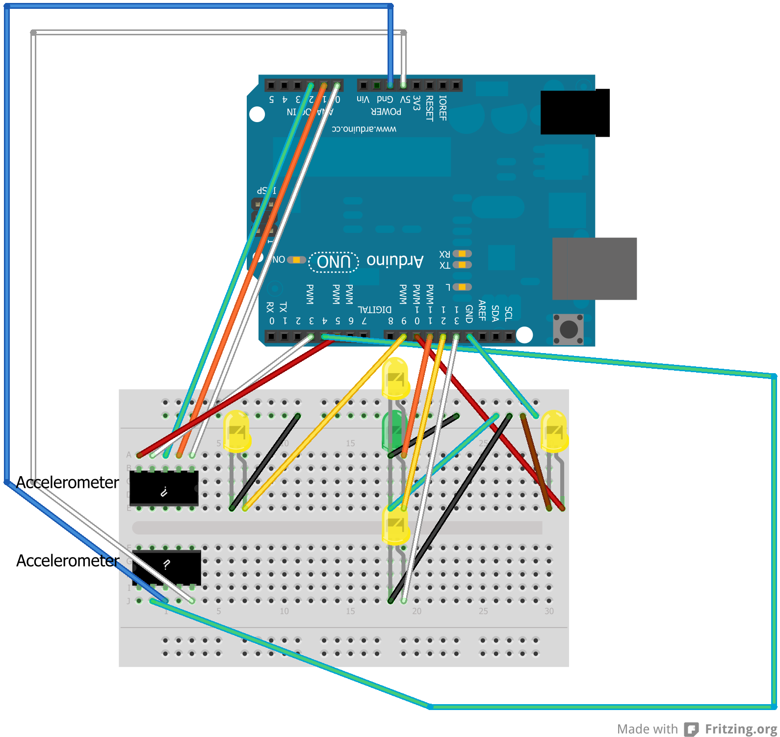
Since this is just a simple primer, I won't go into great detail. Basically we need to wire up the accelerometer as outlined in the Arduino sketch and we need to wire up each LED to an output pin and ground. If you need help with the wiring, here's a rough diagram. Note - Fritzing didn't include a piece that was identical to my accelerometer, so I used two 5 pin components - they represent one piece. Also, the wire colors don't have any logical meaning, they match my real-world build.
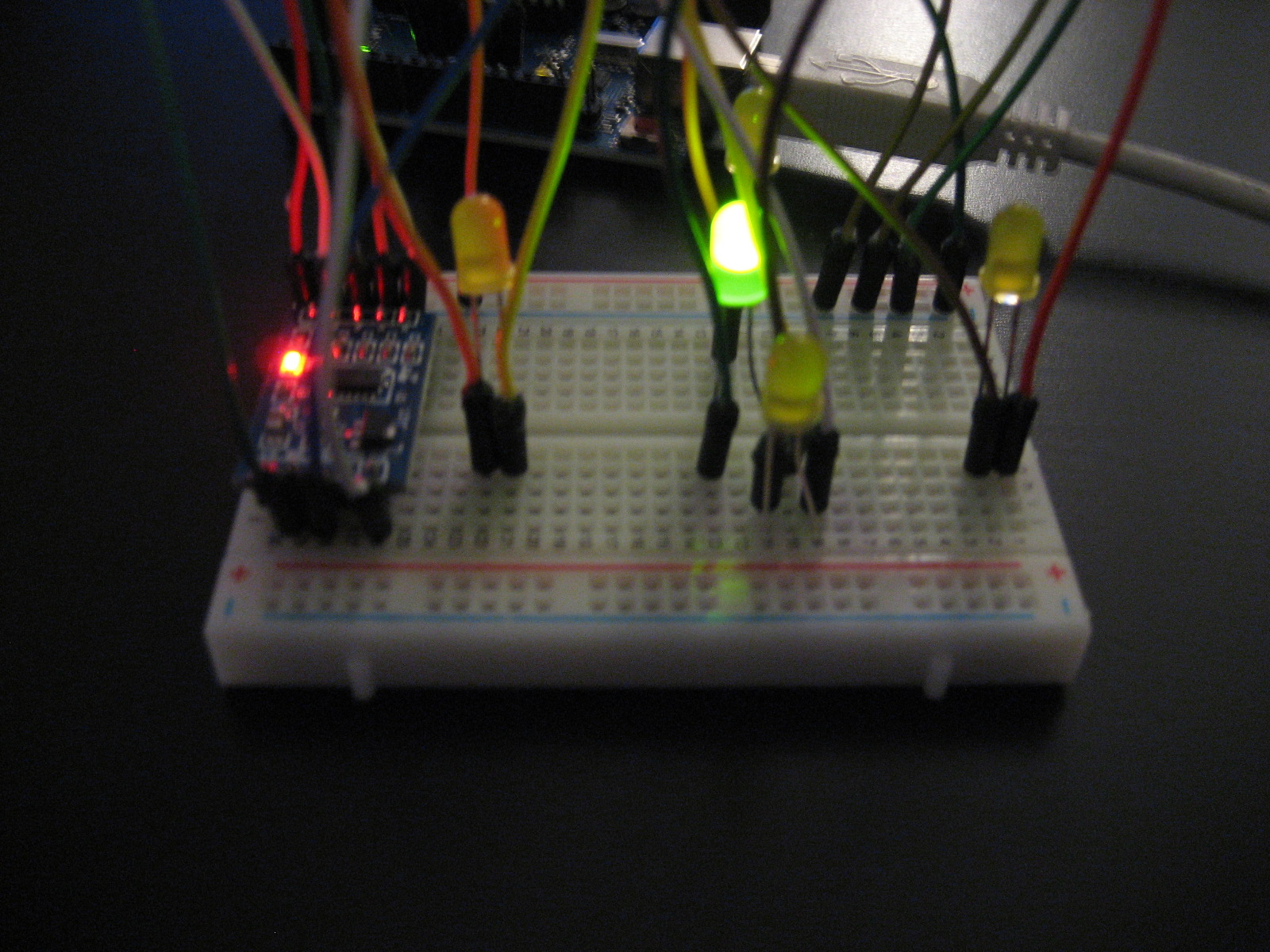
Here's what it looks like up close.
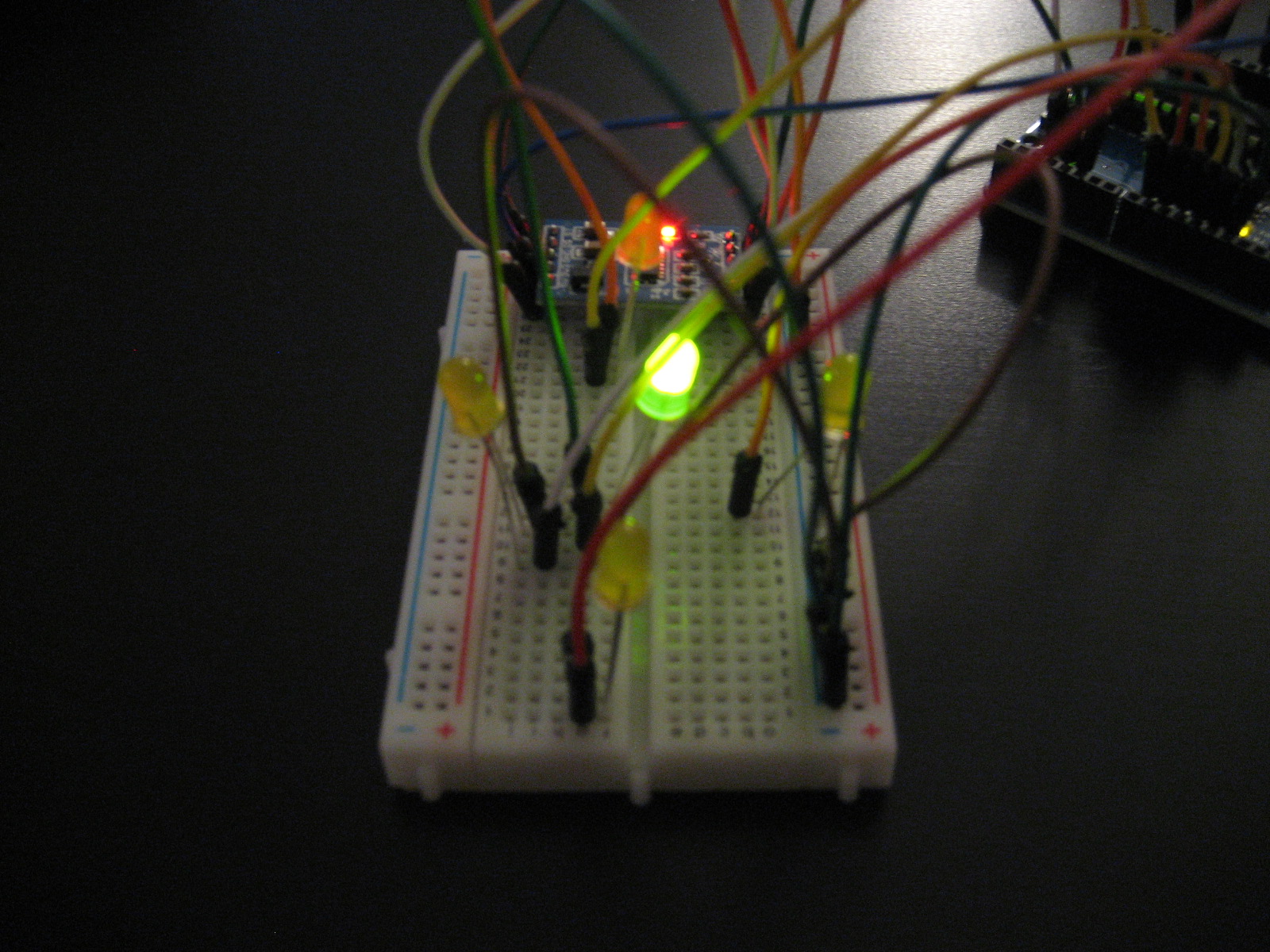
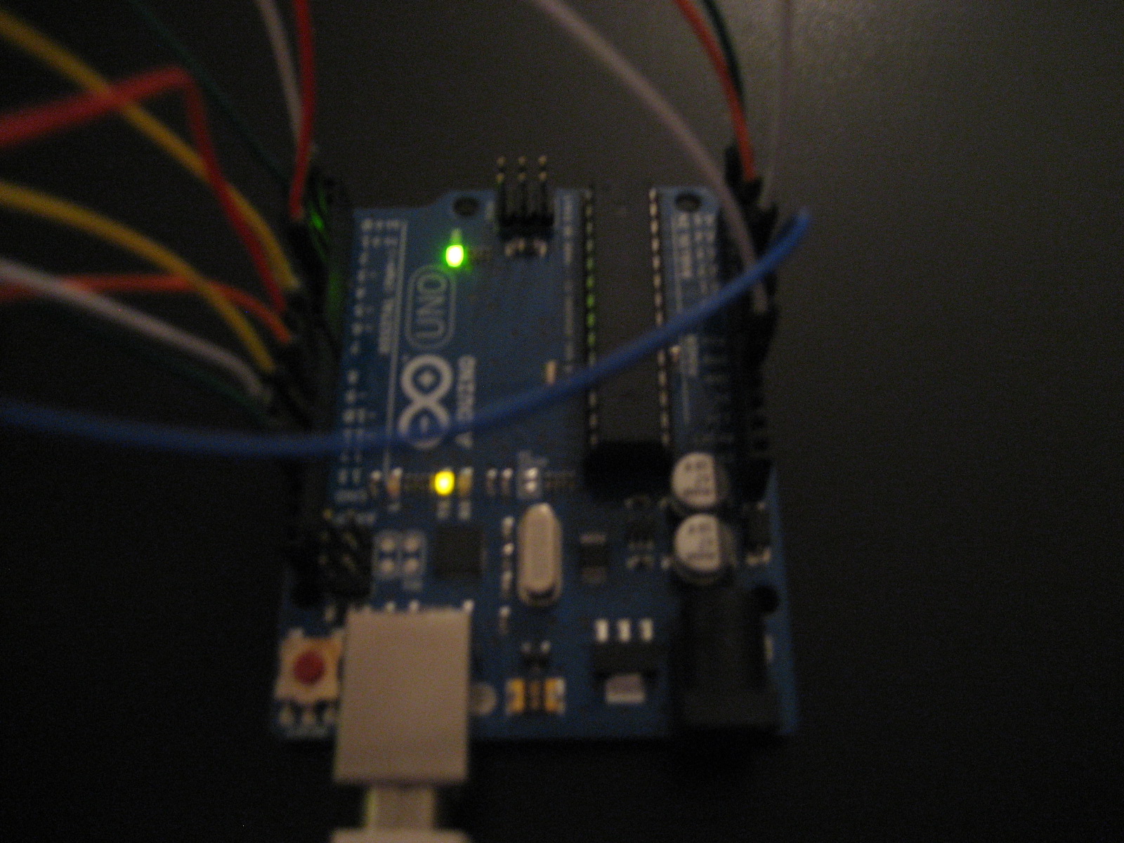
Here are a couple more angles of the wiring:
As far as the programming goes, I started with the example on this page of the Virtuabotix wiki. Here's the my finished sktech:
/*####################################################################
accelerometerPrimer
Alex Glover
January 2013
Based on autoCalibration.ino, provided by virtuabotix
#######################################################################*/
#include "Accelerometer.h"
Accelerometer myAccelerometer = Accelerometer();
int yPosPin = 11;
int yNegPin = 13;
int xPosPin = 10;
int xNegPin = 9;
int zPin = 12;
void setup()
{
  Serial.begin(9600);
  //Connect up the following pins and your power rail
  // SL GS 0G X Y Z
  myAccelerometer.begin(3, 4, 5, A0, A1, A2);
  pinMode(yPosPin, OUTPUT);
  pinMode(yNegPin, OUTPUT);
  pinMode(xPosPin, OUTPUT);
  pinMode(xNegPin, OUTPUT);
  pinMode(zPin, OUTPUT);
  //calibration performed below
  Serial.println("Please place the Accelerometer on a flatnLevel surface");
  delay(2000);//Give user 2 seconds to comply
  myAccelerometer.calibrate();
}
void loop()
{
  delay(20);//delay for readability
  myAccelerometer.read();
  if(myAccelerometer._Zgs <= -0.9){ digitalWrite(zPin, HIGH); } else if(myAccelerometer._Zgs > -0.9){
    digitalWrite(zPin, LOW);
  }
  if(myAccelerometer._Xgs >= 0.5){
    digitalWrite(xPosPin, HIGH);
  }
  else if(myAccelerometer._Xgs < 0.5){
    digitalWrite(xPosPin, LOW);
  }
  if(myAccelerometer._Xgs <= -0.5){ digitalWrite(xNegPin, HIGH); } else if(myAccelerometer._Xgs > -0.5){
  digitalWrite(xNegPin, LOW);
  }
  if(myAccelerometer._Ygs >= 0.5){
  digitalWrite(yPosPin, HIGH);
  }
  else if(myAccelerometer._Ygs < 0.5){
    digitalWrite(yPosPin, LOW);
  }
  if(myAccelerometer._Ygs <= -0.5){
    digitalWrite(yNegPin, HIGH);
  }
  else if(myAccelerometer._Ygs > -0.5){
    digitalWrite(yNegPin, LOW);
  }
}
You can adjust the values to increase/decrease sensitivity. Hope you enjoyed the post, and I hope this helps you jumpstart your project with your accelerometer!
Leave a Comment