
A couple years ago I built a novelty lock box that used an Arduino and an accelerometer so that you had to tilt the box in the correct sequence to unlock it. The prototype was pretty rough, so I eventually refined the design and built a Mark II version of it.
This project is my third iteration of the novelty lockbox. The majority of the design has remain unchanged, except for this project I used a "flame sensor" instead of an accelerometer. Instead of tilting the box in a particular sequence, the only way to open the box is to use an open flame as the "key." Here's a quick video to demonstrate the finished product:
Component List
- A 3-5.5v "flame sensor"
- An Arduino Uno (or materials to build your own breakout board)
- A DC power supply with both 5v and 12v output (I used an old molex power supply)
- A single relay
- A 12v door latch
Testing
Before you do anything with the box, we want to test and calibrate the flame sensor. I followed this Instructable to get acquainted with the flame sensor and what kind of values it returns. Note that the author is mapping the full range of values (0-1024) to just 4 values to match his sketch. Start by modifying this block:
void loop() {
  // read the sensor on analog A0:
  int sensorReading = analogRead(A0);
  // map the sensor range (four options):
  // ex: 'long int map(long int, long int, long int, long int, long int)'
  int range = map(sensorReading, sensorMin, sensorMax, 0, 3);
by adding a line for logging the raw sensor reading, like this:
void loop() {
  // read the sensor on analog A0:
  int sensorReading = analogRead(A0);
  Serial.println(sensorReading);

  // map the sensor range (four options):
  // ex: 'long int map(long int, long int, long int, long int, long int)'
  int range = map(sensorReading, sensorMin, sensorMax, 0, 3);
Now you can wire up the sensor, upload your sketch, and experiment with what kind of values you get with an open flame at different distances.
One quick clarification - I refer to this device as a "flame sensor" because that's how its marketed, but in reality it's just a photoresistor that has a filtering film around it that only allows infrared light to pass through. The voltage in the photoresistor circuit will change with the amount of light, and the Arduino analog pin will convert that voltage value to an integer between 0 and 1024. This means any infrared light will affect the sensor, including sunlight, TV remotes that use infrared, even something that is very hot could theoretically give off enough infrared to affect the sensor. If you're getting strange values while testing your sensor, be sure that you don't have another source of infrared throwing you off.
Once you're confident your sensor works and you have some idea of what values it returns, you're ready to build out the lock box components.
Assembly
Note: To save on cost, I've been building Arduino compatible breadboards using standalone ATmega328 chips. The instructions will still work for an Arduino Uno, but the pictures won't be as helpful. Check out Arduino Project 4: Tilt to Unlock to see pictures for a similar assembly using an Arduino Uno.
-
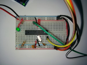
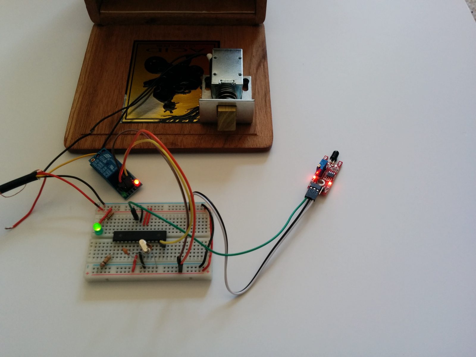
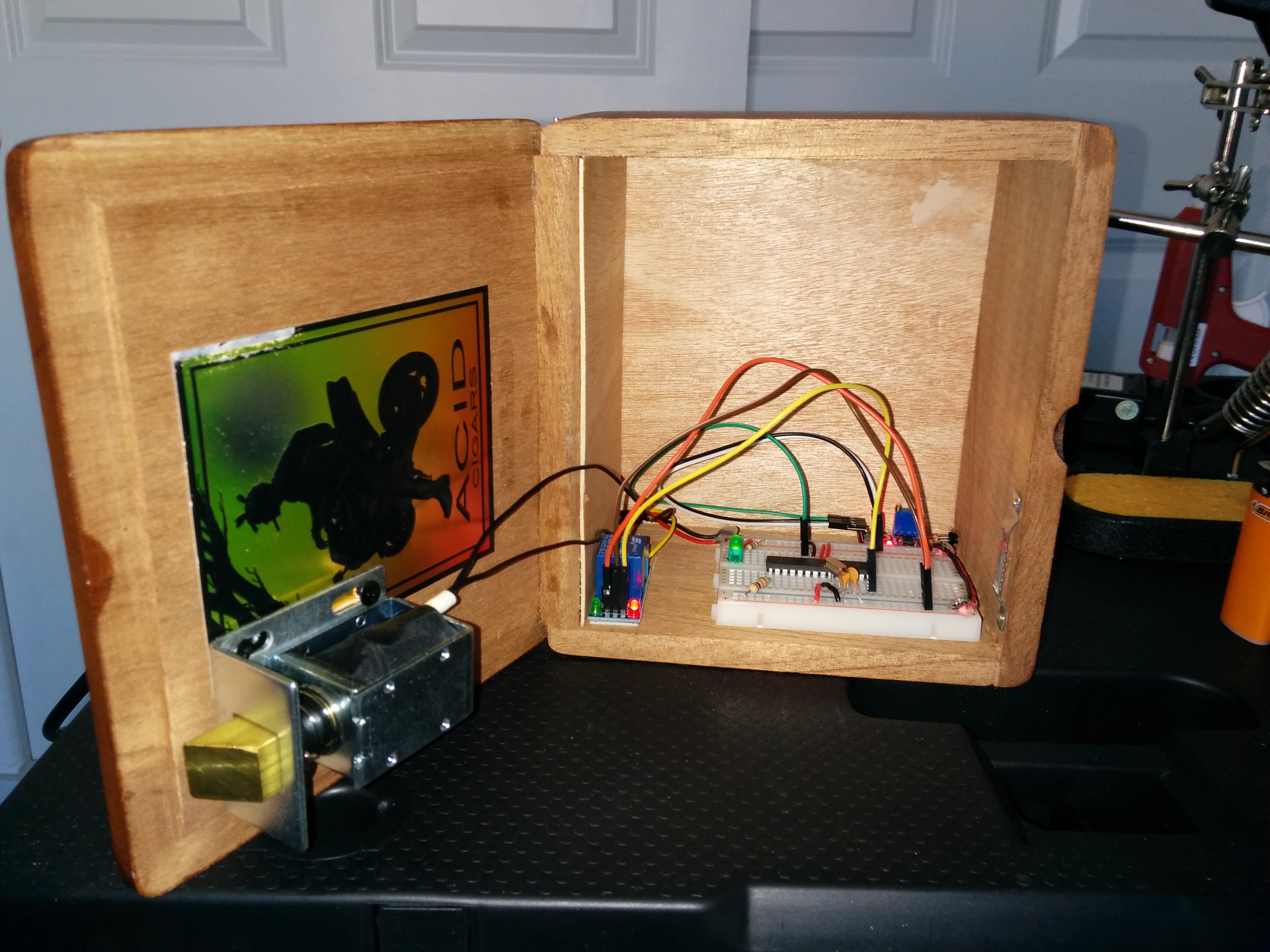
Connect the 5v and ground pins (may be marked as '+' and 'G') on your flame sensor to the corresponding pins on the Arduino or bread board. Connect the A0 pin (the analog pin) on the flame sensor to the Analog Input 0 pin on the Arduino (green wire in the photo below, pin 23 on an ATmega328). Use male-to-female jumper wires to make this easier.
-
Connect the 5v and ground pins (may be marked as 'VCC' and 'GND') on the relay to the corresponding pins on the Arduino or bread board. Connect the 'IN' pin to Digital Pin 8 (yellow wire in the photo above, pin 14 on an ATmega328). The digital pin will close the relay when voltage is applied, closing the circuit for our door latch and opening the lock. Use male-to-female jumper wires to make this easier.
-
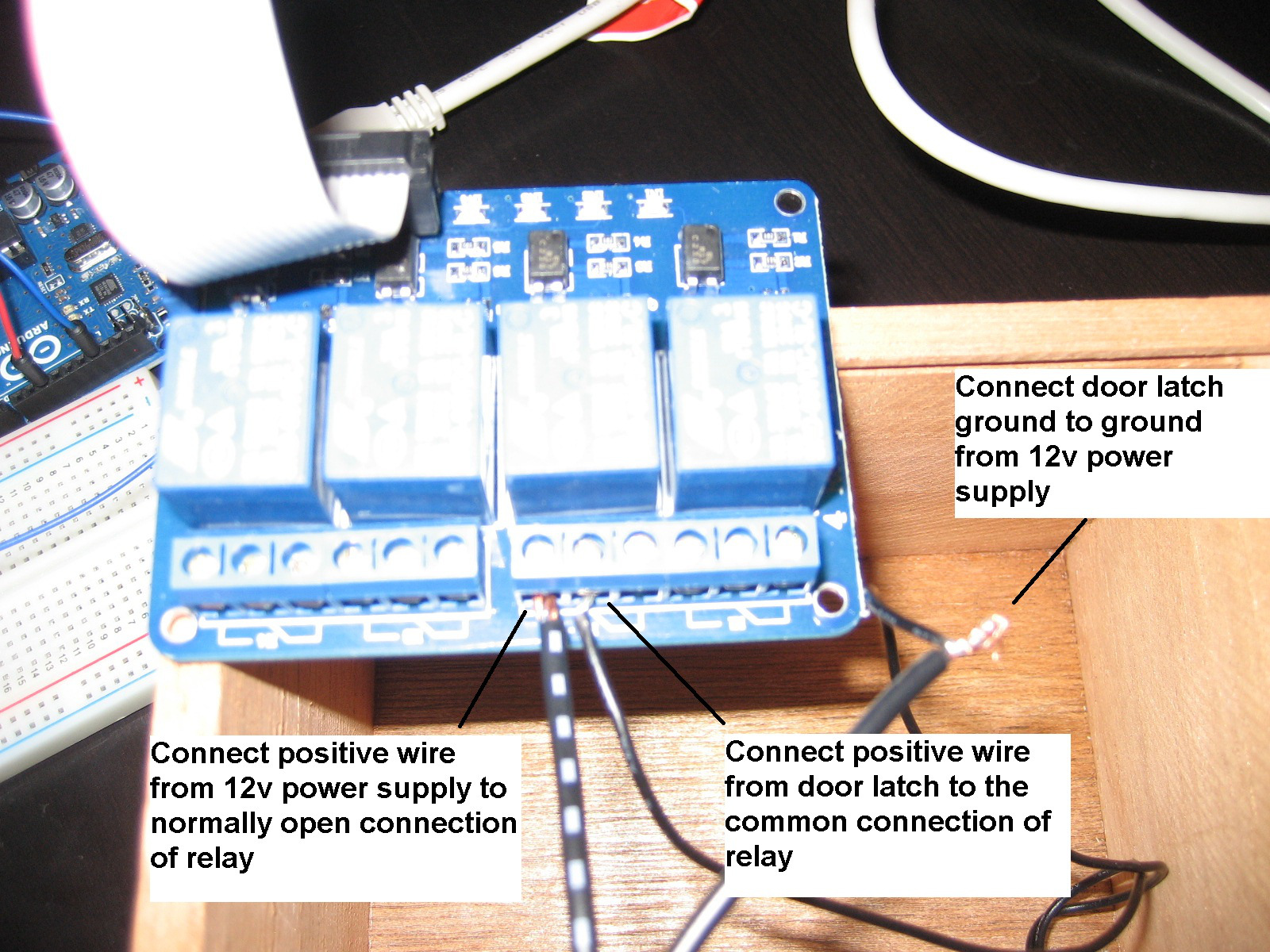
The door latch has two wires, they are arbitrary (either one can be powered or ground). Connect one of them to the ground wire from the power supply. Connect the other wire to the normally open ('NO') socket on the relay. Connect the 12v wire from the power supply to the always-closed or common socket on the relay (it's almost always the middle one). Here's a closeup of the wiring from Arduino Project 4:

So our project should be all wired up and ready for a smoke test. Go ahead and connect the power and make sure nothing starts smoking or getting too hot.
- If you're still reading that means nothing melted or started smoking, which is great. At this point we're ready to upload a sketch and test. Go ahead and download the sketch and upload it to your Arduino. If all goes well, the door latch should open when you provide the infrared light. Here's a quick test video:
Now we're ready to assemble the box.
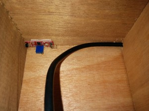
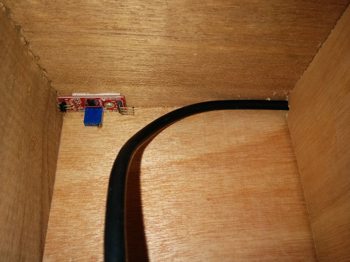
- Drill a hole in the back of the cigar box just big enough to run your power supply wires through, including the insulation. Run your wire through and let it hang outside of the box for later (this will also prevent you from locking yourself out of the box by accident).
-
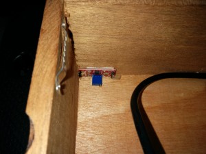
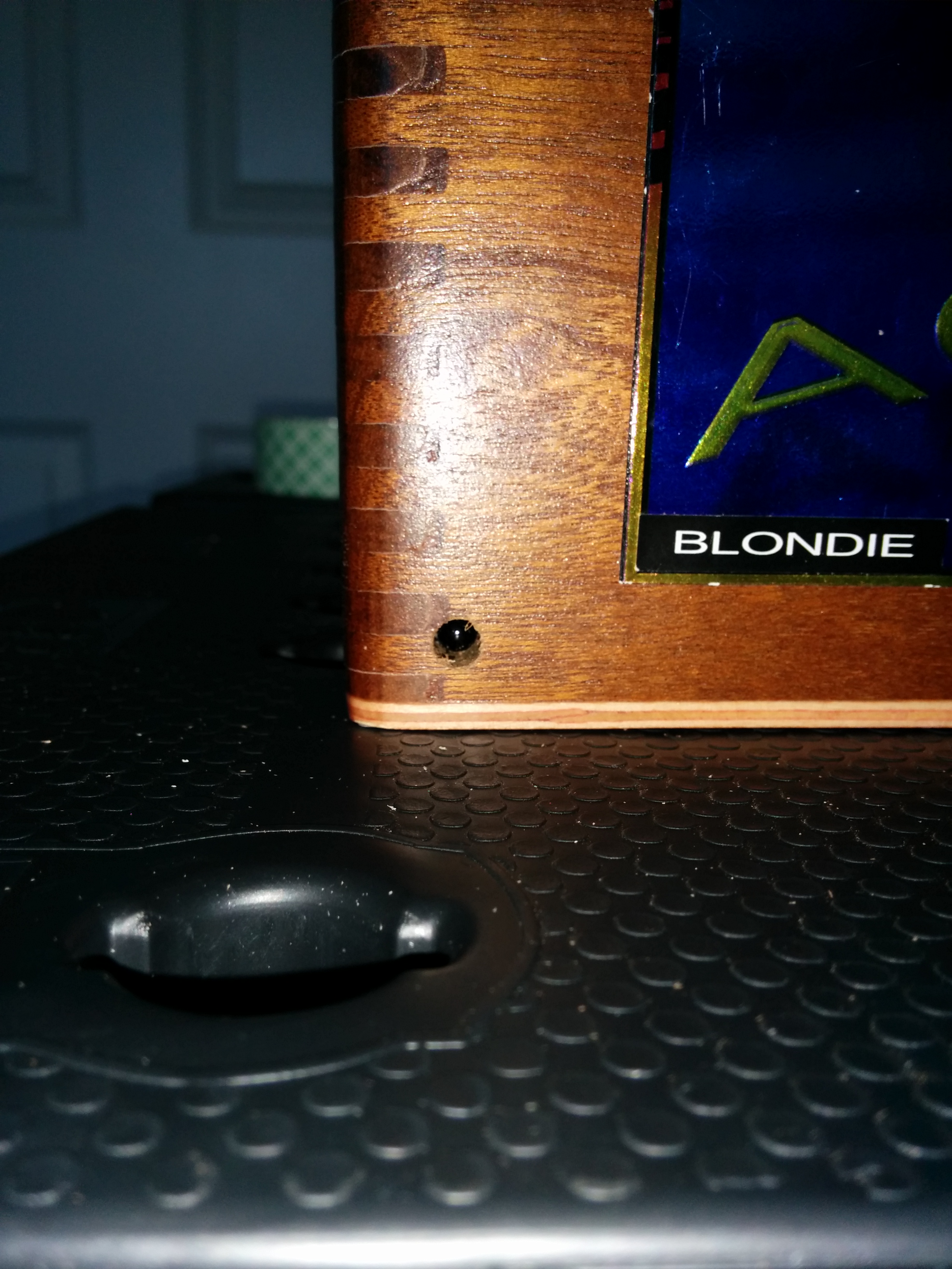
Remember how I mentioned other sources of infrared can interfere with your sensor? We can limit this effect by "tunneling" or narrowing the sensor's field of view. Start off by drilling a small hole in your cigar box. A 1/4" inch drillbit should work well for this. Make sure your hole placement lines up with a reasonable place to mount your flame sensor inside of the box. To be discreet, I drilled my hole on the bottom left of the "face" of the cigar box and mounted the sensor using double sided tape.

-
If you're starting with a "clam-shell" style box (cigar boxes work great), you can follow my solution for the door latch. Secure the 12v door latch to the top of the cigar box with 1/4" screws. Next, take a sawtooth picture hangar and nail it into place so it lines up with the 12v door latch. Obviously hammering inside of a cigar box can be difficult - you can also use a pair of pliers to squeeze the nail into place.
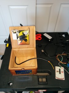
-
At this point, things are going to start getting tight so go ahead and re-wire everything outside of the box. Once you're finished, mount your Arduino (or breadboard) and relay inside of the box. Try to keep all of these components mounted off to one side to save as much usable space as possible.

I mounted all of my components to the side of the cigar box. Make sure your 12v door latch won't hit your other components when you close the box.


That's it, your lock box is complete! As always I hope you enjoyed the post and I look forward to seeing what you build!
Leave a Comment