
Arduino Project 4: Tilt To Unlock
This is my favorite Arduino project to date. After some basic experimenting with an accelerometer, I had an idea. What if you used the accelerometer to look for a combination of movements? Instead of using a combination lock or a traditional key lock, you could just tilt the object in a set pattern to unlock it. Here's what I ended up with:
Pretty sweet if you ask me.
Note - in spite of my terrible, coffee-fueled, shakey-handed videography, a lot of this post will be in video form.
Now this post is based on my Acclerometer Primer, so if you're following along and want to build one of these for yourself you should go back and build the primer.
Parts Used (beyond what was used in the primer)
- Amico DC 12V Open Frame Type Solenoid for Electric Door Lock
- SainSmart 4-Channel 5V Relay Module (any 5v relay will work, we won't use all 4 channels)
- 12v Power Supply (you can use a battery or wall adapter)
- Some sort of box/container - something larger than 4in x 4in x 4in, otherwise you may have trouble getting all of the components in
Phase 1 - Adapting the Primer To Recognize a Combination
Before we try to add any new hardware, let's modify the Accelerometer Primer code to look for a pattern of movements. We've already got the mechanism for recognizing simple single movements, so all we need is to add some code to track multiple movements relative to each other. I just added a new integer variable called "currentMove." currentMove will get incremented each time a correct move in the sequence is made. To thwart people from just shaking the box or trying random patterns, each incorrect move will reset currentMove to 1. Let's see it in action:
Here's my code:
/*####################################################################
Tilt To Unlock
Alex Glover
February 2013
Combination to unlock box is Y+ (left), X+ (forward), Y+ (left), X- (back), Y+ (forward)
Based on autoCalibration.ino, provided by virtuabotix
#######################################################################*/
#include "Accelerometer.h"</code>
Accelerometer myAccelerometer = Accelerometer();
int yPosPin = 11;
int yNegPin = 13;
int xPosPin = 10;
int xNegPin = 9;
int zPin = 12;
int currentMove = 1;
int resetTrigger = 0;
void setup()
{
  Serial.begin(9600);
  //Connect up the following pins and your power rail
  // SL GS 0G X Y Z
  myAccelerometer.begin(3, 4, 5, A0, A1, A2);
  pinMode(yPosPin, OUTPUT);
  pinMode(yNegPin, OUTPUT);
  pinMode(xPosPin, OUTPUT);
  pinMode(xNegPin, OUTPUT);
  pinMode(zPin, OUTPUT);
  //calibration performed below
  Serial.println("Please place the Accelerometer on a flatnLevel surface");
  delay(2000);//Give user 2 seconds to comply
  myAccelerometer.calibrate();
}
void loop()
{
  delay(20);//delay for readability
  resetTrigger++; //increment the reset trigger
  myAccelerometer.read();
  if(myAccelerometer._Zgs <= -0.9){ digitalWrite(zPin, HIGH); } else if(myAccelerometer._Zgs > -0.9){
    digitalWrite(zPin, LOW);
  }
  if(myAccelerometer._Xgs >= 0.5){
    digitalWrite(xPosPin, HIGH);
    if(currentMove==2){
      Serial.println("Second move successful");
      currentMove++;
      delay(1000);
    }
    else if(currentMove==5){
      Serial.println("Fifth move successful - opening");
      currentMove++;
      delay(1000);
    }
    else{
      Serial.println("WRONG MOVE!");
      currentMove=1;
    }
  }
  else if(myAccelerometer._Xgs < 0.5){
    digitalWrite(xPosPin, LOW);
  }
  if(myAccelerometer._Xgs <= -0.5){
    digitalWrite(xNegPin, HIGH);
    if(currentMove==4){
      Serial.println("Fourth move successful");
      currentMove++;
      delay(1000);
    }
    else{
      Serial.println("WRONG MOVE!");
      currentMove=1;
    }
  }
  else if(myAccelerometer._Xgs > -0.5){
    digitalWrite(xNegPin, LOW);
  }
  if(myAccelerometer._Ygs >= 0.5){
    digitalWrite(yPosPin, HIGH);
    if(currentMove==1){
      Serial.println("First move successful");
      currentMove++;
      delay(1000);
    }
    else if(currentMove==3){
      Serial.println("Third move successful");
      currentMove++;
      delay(1000);
    }
    else{
      Serial.println("WRONG MOVE!");
      currentMove=1;
    }
  }
  else if(myAccelerometer._Ygs < 0.5){
    digitalWrite(yPosPin, LOW);
  }
  if(myAccelerometer._Ygs <= -0.5){
    digitalWrite(yNegPin, HIGH);
    Serial.println("WRONG MOVE!");
    currentMove=1;
  } else if(myAccelerometer._Ygs > -0.5){
    digitalWrite(yNegPin, LOW);
  }
  if(resetTrigger==3000){ //do this every minute (3000 iterations * 0.02 seconds = 60 seconds)
    currentMove=1; //reset currentMove back to 1, so user can try to do the sequence again
    resetTrigger=0; //set the resetTrigger back to 0 so it can start another iteration to 3000
  }
}
Perfect! Now we can recognize a combination of movements. Now all we need to do is something meaningful when the combination is recognized.
Phase 2 - Incorporating The Cigar Box, Relay, and 12v Door Latch
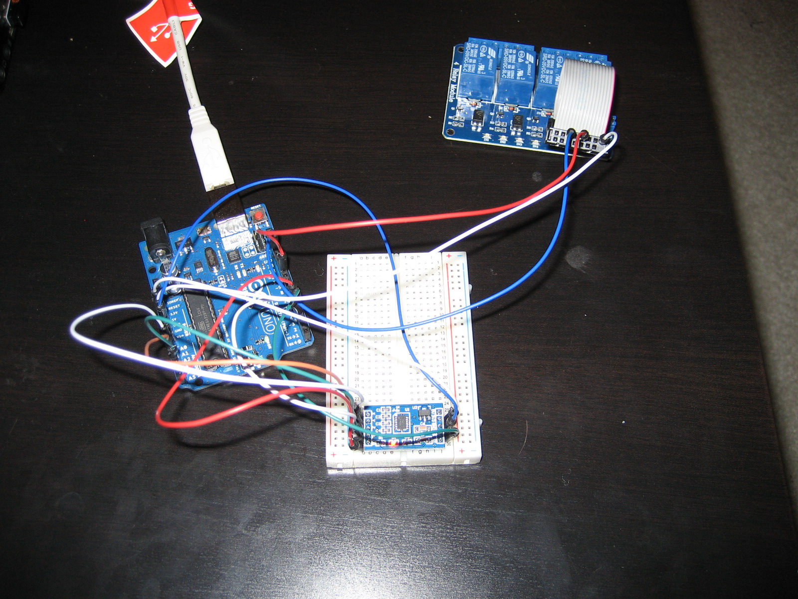
Time for the hardware. Now, at this point we should be pretty confident in our code (we are confident in our code, right?) so we can get rid of the LEDs and all of the associated jumper wires. Next, switch your Virtuabotix Accelerometer from using the 5v power from the Arduino to using the 3.3v power from the Arduino (you'll need to change the connection at both ends, since the accelerometer has connections for both). We need to switch to 3.3v because our relay is going to use the 5v power from the Arduino. That being said, connect the 5v power to the VCC pin on the relay and also connect the ground from your Arduino to the relay. Next, choose one of the digital pins from your Arduino (doesn't matter which) and connect it to the relay control connections - this pin will control the opening and closing of your relay circuit. In my case, I had to use a ribbon cable as an adapter between the male pins on the relay and the male jumper wires. In the picture below, I've removed all of the LEDs and connected the relay (white wire is 5v power to relay, blue is ground, and red wire connects pin 10 to the 3rd relay control).
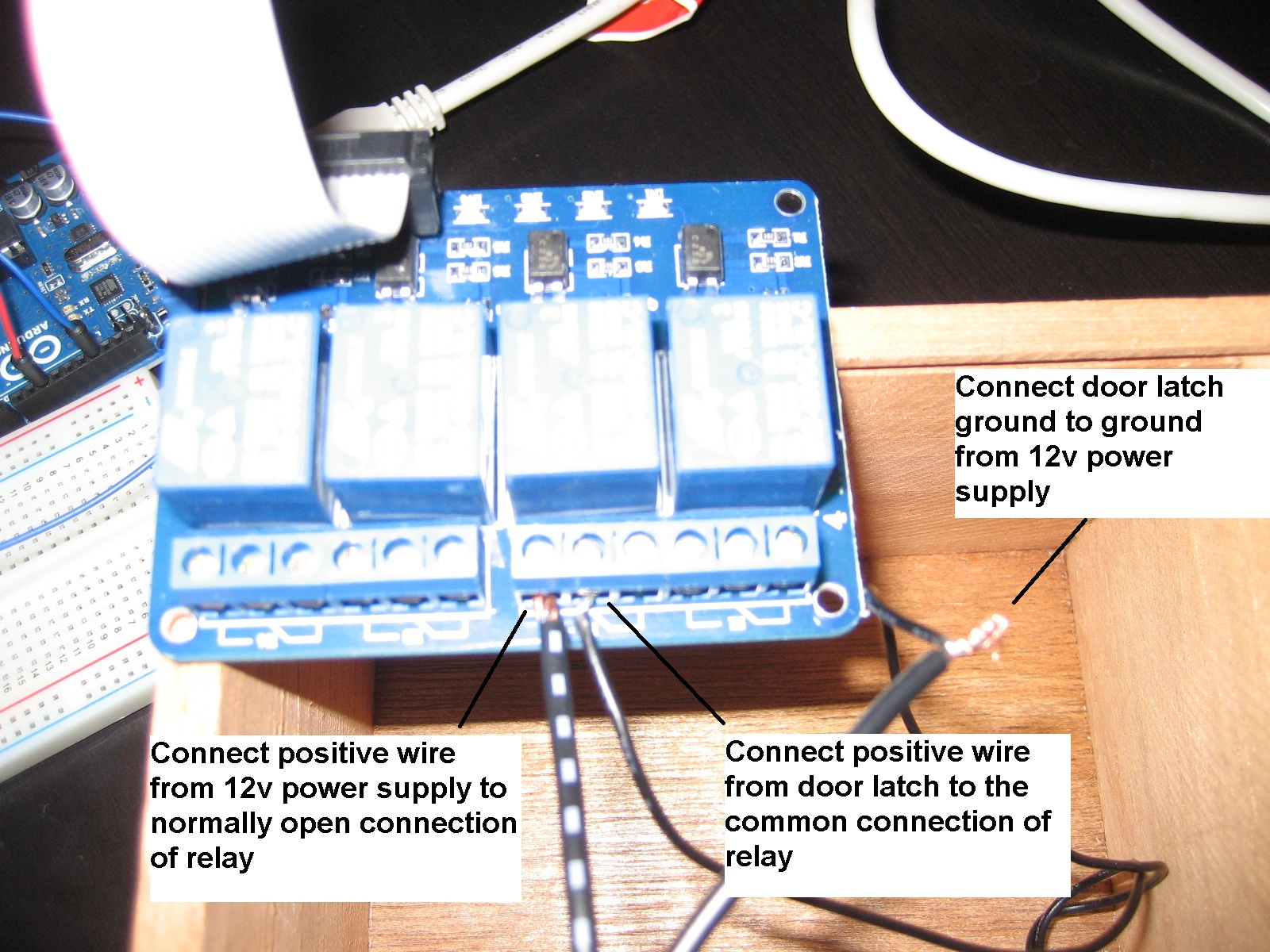
Now might be a good time to mount your 12v door latch. Once mounted, take the ground wire from the door latch and solder/connect it directly to the ground of your 12v power supply. Next, take the voltage-in wire from the door latch and connect it to the middle 'port' of one of your relays. This middle port is the 'common' connection, and it is always connected to the circuit. The other two 'ports' are normally open (NO) and normally closed (NC). Normally open means that the circuit is open (no current flowing through) when the relay is not powered; once the relay is powered by the 5v connection from the Arduino, the circuit closes and current flows through. The normally closed port is the opposite - current is flowing through until the relay gets a 5v signal, at which point it breaks (opens) the circuit. In our case, we want to connect the positive wire from the 12v power supply to the normally open contact. Here's a quick diagram to help:
We've just covered a lot so here's a quick recap video to bring it all together:
Alright, if you've managed to get all of the hardware put together, all you need is a little more code to interact with the relay and door latch. Here's my code:
/*####################################################################
tiltToUnlock
Alex Glover
February 2013
Combination to unlock box is Y+ (left), X+ (forward), Y+ (left), X- (back), Y+ (forward)
Based on autoCalibration.ino, provided by virtuabotix
#######################################################################*/
#include "Accelerometer.h"
Accelerometer myAccelerometer = Accelerometer();
/*int yPosPin = 11;
int yNegPin = 13;
int xPosPin = 10;
int xNegPin = 9;
int zPin = 12;
We don't need any of these pins anymore, as we're not using LEDs*/
int currentMove = 1;
int resetTrigger = 0;
int relayPin = 10;
void setup()
{
  Serial.begin(9600);
  //Connect up the following pins and your power rail
  // SL GS 0G X Y Z
  myAccelerometer.begin(3, 4, 5, A0, A1, A2);
  /*pinMode(yPosPin, OUTPUT);
  pinMode(yNegPin, OUTPUT);
  pinMode(xPosPin, OUTPUT);
  pinMode(xNegPin, OUTPUT);
  pinMode(zPin, OUTPUT);
  We don't need any of these pins anymore, as we're not using LEDs*/
  pinMode(relayPin, OUTPUT);//Set the pin that will control the relay in OUTPUT mode
  digitalWrite(relayPin, HIGH);//Write a high voltage signal to the relay on startup - this will break the circuit
  //calibration performed below
  Serial.println("Please place the Accelerometer on a flatnlevel surface");
  delay(2000);//Give user 2 seconds to comply
  Serial.println("Calibration complete");
  myAccelerometer.calibrate();
}
void loop()
{
  delay(20);//delay for readability
  resetTrigger++; //increment the reset trigger
  myAccelerometer.read();
  if(myAccelerometer._Zgs -0.9){
    //digitalWrite(zPin, LOW);
  }
  if(myAccelerometer._Xgs >= 0.5){
    //digitalWrite(xPosPin, HIGH);
    if(currentMove==2){
      Serial.println("Second move successful");
      currentMove++;
      delay(1000);
    }
    else if(currentMove==5){
      Serial.println("Fifth move successful - opening");
      currentMove=1;
      digitalWrite(relayPin, LOW);
      delay(2000);
      digitalWrite(relayPin, HIGH);
      delay(1000);
    }
    else{
      Serial.println("WRONG MOVE!");
      currentMove=1;
    }
  }
  else if(myAccelerometer._Xgs < 0.5){
    //digitalWrite(xPosPin, LOW);
  }
  if(myAccelerometer._Xgs -0.5){
    //digitalWrite(xNegPin, LOW);
  }
  if(myAccelerometer._Ygs >= 0.5){
    //digitalWrite(yPosPin, HIGH);
    if(currentMove==1){
      Serial.println("First move successful");
      currentMove++;
      delay(1000);
    }
    else if(currentMove==3){
      Serial.println("Third move successful");
      currentMove++;
      delay(1000);
    }
    else{
      Serial.println("WRONG MOVE!");
      currentMove=1;
    }
  }
  else if(myAccelerometer._Ygs < 0.5){
    //digitalWrite(yPosPin, LOW);
  }
  if(myAccelerometer._Ygs -0.5){
    //digitalWrite(yNegPin, LOW);
  }
  if(resetTrigger==3000){ //do this every minute (3000 iterations * 0.02 seconds = 60 seconds)
    currentMove=1; //reset currentMove back to 1, so user can try to do the sequence again
    resetTrigger=0; //set the resetTrigger back to 0 so it can start another iteration to 3000
  }
}
Awesome. One thing I almost forgot to mention - the 12v door latch needs something to latch on. You may have to get creative with this part, depending on what kind of box you are using. In my case, the cigar box lid actually slid off (rather than opening on hinges) so all I had to do was carve a notch into the lid for the latch to catch on.
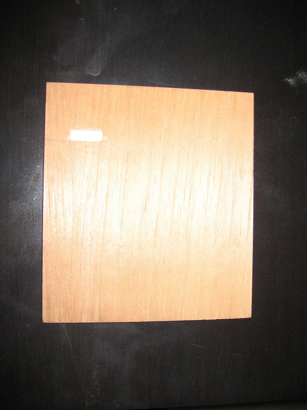
Now when I slide the lid of the box again, it pushes the latch down until it lines up with the notch and then *click*, it latches and locks the box closed.
Whew. Long write-up. If I missed anything or if you have any questions, feel free to comment and I'll be happy to help!
Update: By connecting both the Arduino and the door latch to the ground and power rails on the breadboard, I was able to do away with the 9v battery altogether. Now you don't have to worry about the battery dying and the box being locked forever.
Leave a Comment