
Arduino Project 2: The Audible Eye Part 1
The Audible Eye is a short proof-of-concept project that I came up with while looking for ways to experiment with some new gear. The idea of combining an ultrasonic rangefinder and some sort of signaling audio output jumped out to me - it would give you a depth perception, not unlike echo location that bats and dolphins use. As far as practical use, I believe it could be used by the visually impaired as a complement to a white cane, but not as a replacement.
Basically, the tone/pitch of the audio signal would get higher as the operator moves closer to a wall or object, indicating to the operator that they are getting closer. Similarly, as the operator moves away from the wall the tone will drop until it's almost inaudible.
Let me provide some context to make this more clear. Let's imagine our operator is blindfolded. If the operator pointed the device down an empty hallway for example, they would hear almost no tone, telling them it's safe to walk forward. As they approached a wall, the tone would increase. The operator would then scan around them with the device, find another path that was unobstructed, and could continue walking.
This video is all but unwatchable (quality is IMPRESSIVELY bad), but it will at least give you an idea of how it works. And of course I disassembled the project before I realized the video was botched.
Alright, let's open up the enclosure and start breaking down the project. The entire project can be broken down into just a few components. Here's a view inside of the enclosure.
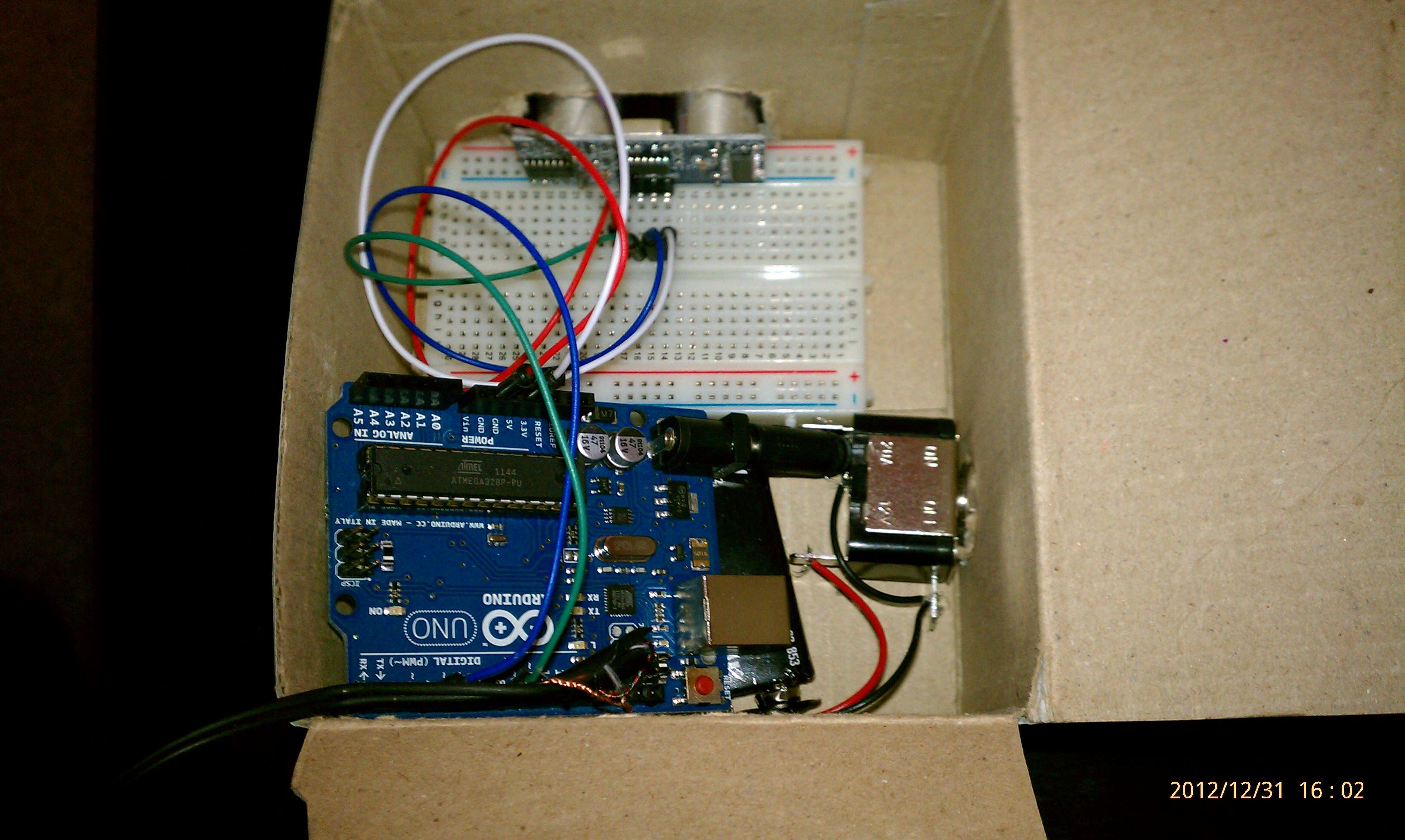
Component List:
- Arduino Uno
- HC-SR04 Ultrasonic Rangefinder
- Breadboard and jumper wires
- 9v Battery Adapter
- 3 Pin Toggle Switch
- 9v Battery (stop putting it on your tongue)
- Headphones (or any other audio output device)
Building the project can be broken down into phases. Let's focus on the ultrasonic rangefinder first, and build from there.
Setting up the Ultrasonic Rangefinder
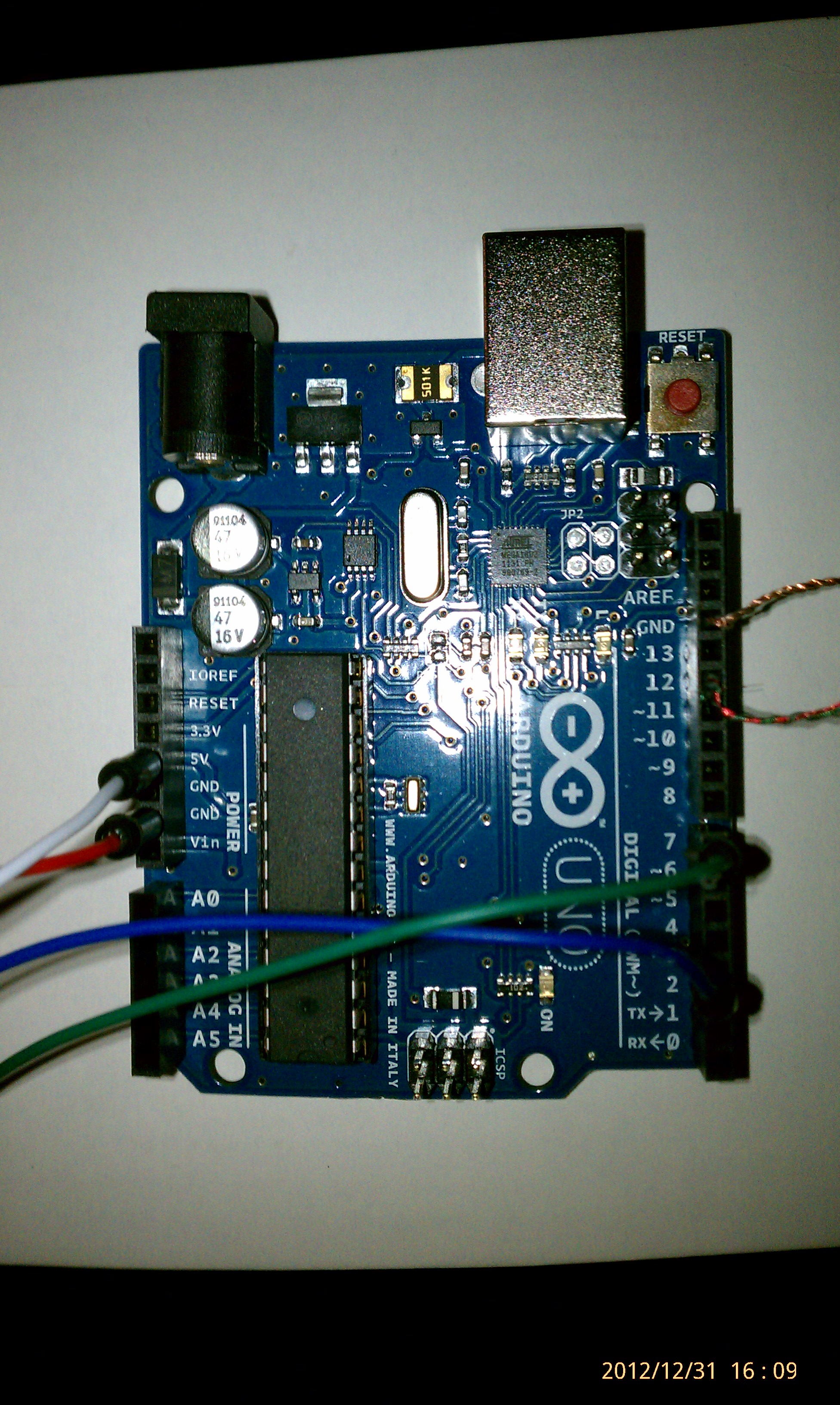
There are 4 pins on the HC-SR04 ultrasonic sensor module: voltage in (labeled "Vcc" on my module), ground, TRIG, and ECHO. The TRIG pin will control the transmission of ultrasound. The ECHO pin will be the receiver pin. Use your jumper wires to connect the ground on the module to the ground on the Arduino (red wire near the top of the above picture) and connect the voltage in pin to the +5v pin on the Arduion (white wire near the top of the above picture). Next, use jumper wires to connect the TRIG and ECHO pins to two of the digital pins on the Arduino. These will be the numbered pins on the Arduino that do NOT have the tilde (~) prefix. In my build, I used pin 2 for the TRIG connection and pin 7 for the ECHO connection. Here's a better picture:
OK we're all wired up! There are several libraries for interacting with ultrasonic rangefinders. The one I used is probably out of date, but you can download it here.
Note: If you're having issues with this library, edit Ultrasonic.cpp and Ultrasonic.h. Replace this line:
#include "WProgram.h"
with this:
#include "Arduino.h"
Once you've downloaded it, add the entire directory (should contain Ultrasonic.h, Ultrasonic.cpp, keywords.txt, and an examples directory) to your Arduino's libraries directory. I'm being lazy and have the Arduino install on my desktop, so my library directory is here:
C:\Users\Alex\Desktop\arduino-1.0.1\libraries\
Once that's done, open up the Arduino IDE. Click on the "Sketch" dropdown menu, click "Import Library" and verify that Ultrasonic is a listed library. If it's there, you're in good shape.
Visit http://arduino-info.wikispaces.com/UltraSonicDistance and check out the Arduino Sketch provided there. Edit the TRIG_PIN and ECHO_PIN variables to coincide with the pins you used (remember I used 2 and 7 in my case). Connect your Arduino via USB and upload the Sketch. Finally, open the serial monitor (Tools dropdown --> Serial Monitor). You should see readings in inches and centimeters being reported back to the serial monitor.
Awesome - this is our first building block.
Setting up the Audio Output
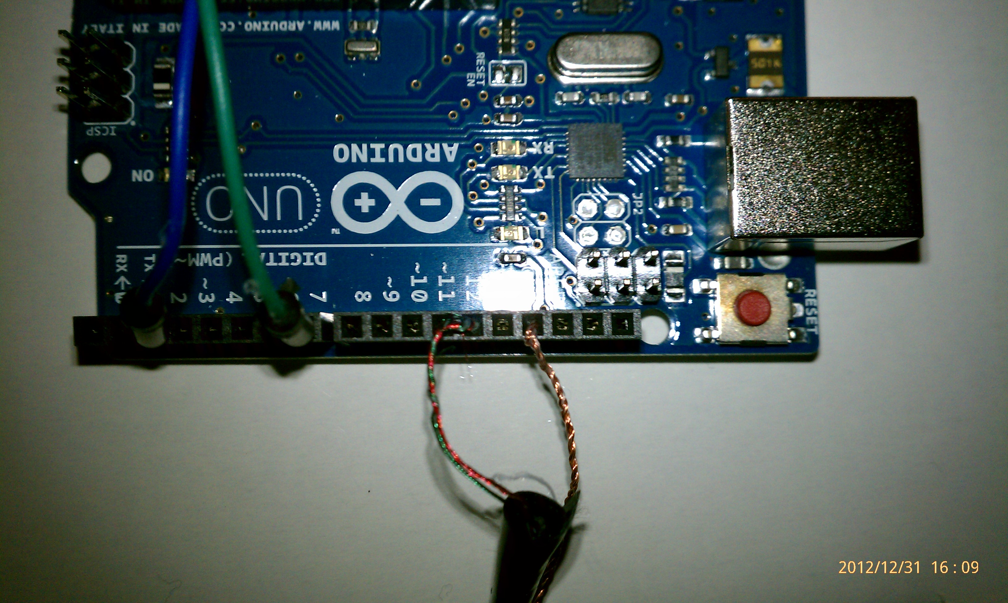
This step is super easy, unless you're me and you waste an hour getting stereo wires confused. If you're using a piezo-electric piece or a simple mono-speaker or headphones, there should be only 2 wires - a voltage in and a ground. Simple. Now, the scrap headphones I had were stereo headphones, which threw me off. If you have a stereo device, you'll likely have 2 separate insulated sections with 2 types of wiring each. In each insulated wire is one plain copper wire and one painted wire. The copper wires are both grounds and the painted wires are the right and left voltage-in connections. Since we're just doing simple mono output, go ahead and twist the two copper wires together and twist the two painted wires together. Next, connect the copper ground wires to one of the grounds on the Arduino. For the voltage-in wires, connect them to one of the PWM pins on the Arduino (I used pin 11). Here's a closeup of the headphone wiring:
Now to test! Conveniently, the Arduino IDE (at least version 1.01) includes a few audio output sketches. Go to File --> Examples -->2. Digial --> Tone Melody. Search the Sketch for the tone() function - change the pin number in each of these functions to coincide with the pin you connected your headphones/speaker to. Now upload the Sketch to your Arduino - if everything is working, you should hear some the melody of "Shave and a haircut, two bits."
Awesome - now we have two of our building blocks completed.
Cliffhanger! In part 2, we'll wire up the toggle switch and battery, as well as write the code to combine the rangefinder and the headphones to complete "The Audible Eye."
Leave a Comment